


MOXA ICF-1170I Series
Industrial CAN-to-fiber converters

 Properties
 Description
 Further Information
 Similar products
 Print this page
 Request Price
 show my notes
 PDF
PDF
 Properties
 Description
 Further Information
 PDF
PDF
- Transmits up to 2 km over optical fiber
- Converts CAN signals to fiber and fiber to CAN signals
- Baudrate up to 1 Mbps
- Dual power inputs for redundancy
- DIP switch for 120 Ù terminal resistance
- DIP switch for fiber test mode
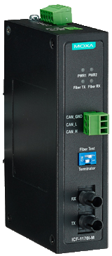
- LEDs for Fiber TX, Fiber RX, Power 1, Power 2
- Wide temperature model available for -40 to 85°C environments
- Fully compatible with the ISO 11898 standard
The ICF-1170I series CAN-to-fiber converters are used to convert CAN signals from copper to optical fiber. The converters come with 2 KV optical isolation for the CANbus system and dual power inputs with alarm contact relay to ensure that your CANbus system will remain online.
Fiber Test Mode can be used to test the fiber cable between two ICF-1170I units, and provides a simple way to determine if the fiber cable is transmitting data correctly. When in Fiber Test Mode, the fiber transceiver (TX) will continuously send out a data signal and the Fiber TX LED will light up. On the other side of the connection, when the ICF-1170I fiber transceiver (RX) receives the data signal form the TX side, the Fiber RX LED will light up.
Fiber Test Mode can be used to test the fiber cable between two ICF-1170I units, and provides a simple way to determine if the fiber cable is transmitting data correctly. When in Fiber Test Mode, the fiber transceiver (TX) will continuously send out a data signal and the Fiber TX LED will light up. On the other side of the connection, when the ICF-1170I fiber transceiver (RX) receives the data signal form the TX side, the Fiber RX LED will light up.
CAN Communication
CAN Interface
ISO 11898-2, Terminals (CAN_H, CAN_L,CAN_GND)
Protocols
CAN 2.0A and 2.0B (ISO 11898-2)
Connector
Type 3-pin removable screw terminal x1
Termination Resistor
Dip switch selector for 120 Ù terminal resistor
Transfer Rate
Up to 1 Mbps
System Delay
150 ns
Isolation Protection
2 kV
ESD Protection
Supports 15 kV
Transmission Distance
Max 2 km (depends on the data rate and the protocol used)
- Note The transmission distance is limited by the signal rate, as indicated in the ISO 11898-2 standard.
LED Indicators
PWR1, PWR2, Fiber TX, Fiber RX
Fiber Communication
Connector Type
ST (multi-mode) fiber ports
Support Cable
50/125, 62.5/125, or 100/140 ìm (multi-mode)
Wavelength
850 nm
TX Output
Multi-mode (> -5 dBm)
Rx Sensitivity
Multi-mode (-20 dBm)
Physical Characteristics
Housing
Metal
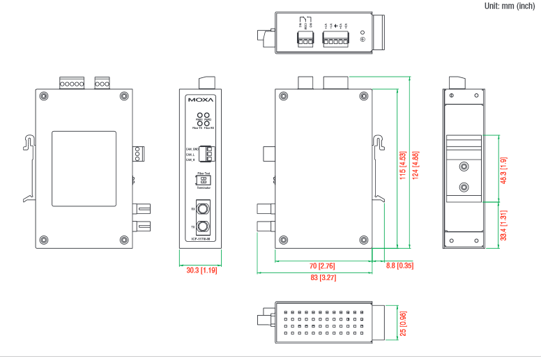
Dimensions
30.3 x 70 x 115 mm (1.19 x 2.76 x 4.53 in)
Environmental Limits
Operating Temperature
Standard Models: 0 to 60°C (32 to 140°F)
Wide Temp. Models: -40 to 85°C (-40 to 185°F)
Storage Temperature
-40 to 85°C (-40 to 185°F)
Ambient Relative Humidity
5 to 95% (non-condensing)
Power Requirements
Input Voltage
12 to 48 VDC dual power inputs for redundant power
Power Consumption
ICF-1170I: 221 mA @ 12 V
Alarm Contact: 1 relay output with current carrying of 1 A @ 24 VDC
Voltage Reversal Protection
Protects against V+/V- reversal
Over Current Protection
1.1 A (protects against two signals shorted together)
Standards and Certifications
Safety
UL 508, EN 60950-1
EMC
CE, FCC
EMI
EN 55022 Class A, FCC Part 15 Subpart B Class A
EMS
EN 61000-4-2 (ESD) Level 4,
EN 61000-4-3 (RS) Level 2,
EN 61000-4-4 (EFT) Level 4,
EN 61000-4-5 (Surge) Level 3,
EN 61000-4-6 (CS) Level 2,
EN 61000-4-8 (PFMF) Level 3
Freefall
IEC 60068-2-32
Green Product
RoHS, CRoHS, WEEE
MTBF (mean time between failures)
Time
792,085 hrs
Database
Telcordia (Bellcore), GB
Ordering Information
| Available Modules | |
| ICF-1170I-M-ST | CANbus to fiber converter, multi-mode, ST connector, 0 to 60°C |
| ICF-1170I-M-ST-T | CANbus to fiber converter, multi-mode, ST connector, -40 to 85°C |
") Customers who viewed this item also viewed
Customers who viewed this item also viewed